Technology Maturation of a Dual-Spinning CubeSat Bus
PI: Kerri Cahoy, Massachusetts Institute of Technology
PI: Kerri Cahoy, Massachusetts Institute of Technology

- TA12 Materials, Structures, Mechanical Systems and Manufacturing
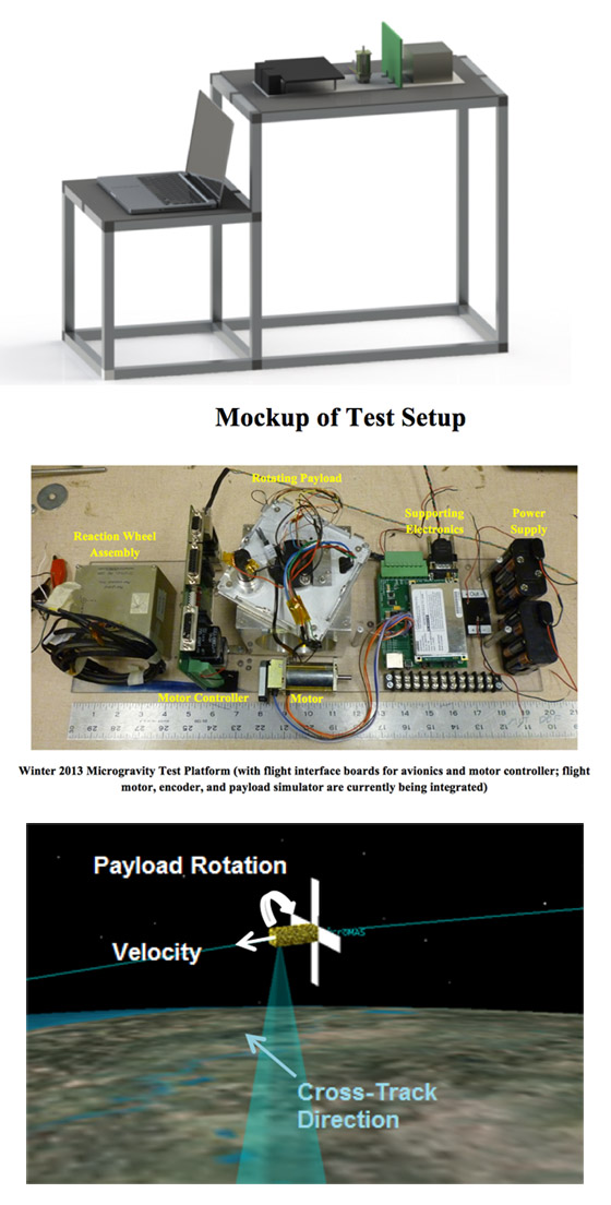
This experiment addresses the need for more capable and enabling Earth sensor platforms on a nano-satellite scale. Our dual-spinning CubeSat consists of a 2U bus and 1U payload. The bus contains all the subsystems necessary for satellite operation (power, communications, avionics, attitude determination and control, and thermal). It houses a scanning assembly, which allows the payload to rotate with respect to the bus. This scanning assembly contains a slipring to accommodate the electrical interface between the payload and bus. The attitude control system is designed to keep the bus 3-axis stabilized for a 60 rpm rotation rate of a 1 kg payload.
The microgravity flight allows us to test and characterize a unique scanner assembly and integrated attitude control system in a relevant environment. The components chosen for the flight assembly are Commercial Of The Shelf (COTS) components, most rated for space with flight heritage. We expect to reach TRL 5 for the entire scanner assembly by the intended microgravity flight opportunity.We hope to reach TRL 6 with the opportunity to experience relevant environmental testing of our prototype.
The first use of this proposed technology is the MicroMAS (Micro-sized Microwave Atmospheric Sounder) CubeSat developed by MIT and MIT Lincoln Laboratory. The payload is a microwave radiometer, and the dual-spinner bus must rotate the payload at a rate of up to 1 Hz while maintaining 1 degree of pointing control. The mission is expected to launch in early 2014. Other potential customers are the cubeSat community and Earth observation scientists.
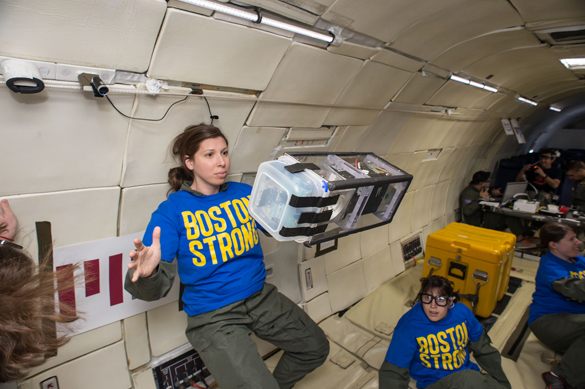
The main purpose of this experiment is to demonstrate that the dual-spinner technology operates as expected in a relevant environment. We will accomplish this by operating the scanner assembly both with the bus constrained and in a free-float configuration. The constrained configuration will isolate the performance of the scanner assembly itself and allow us to characterize the behavior (power draw, speed control) of the motor assembly and the rotating payload dynamics. The free float configuration will allow us to demonstrate the effectiveness of the control algorithms and characterize the behavior (power draw, control limitations) of the attitude control system components. The result of this experiment will be a working knowledge of the expected behavior and limitations of the system that will inform the overall system performance and operation of the demonstration mission.
Specific test objectives are:
- Characterize scanner assembly rotation in microgravity
- Verify control authority of reaction wheel assembly
- Monitor power consumption of relevant components

Technology Details
-
Selection DateAFO6 (Jun 2013)
-
Program StatusCompleted
- 1 Parabolic
Development Team
-
PIKerri Cahoy
-
Organization
-
SponsorMassachusetts Institute of Technology
-
PartnersAnne Marinan
-
More Information

